Learning About The Refrigeration Cycle
Section 1.2 Refrigeration System Review
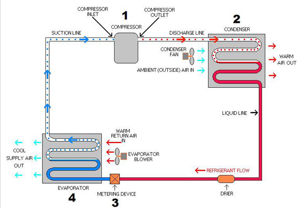
To begin, a refrigeration cycle is “a sequence of thermodynamic processes through which a refrigerant passes, in a closed or open system, to absorb heat at a relatively low temperature level and reject heat at a higher temperature level” (Witt Refrigeration Engineering Manual pg 36) In order to explain this definition in better detail, we provide the following refrigeration diagram:

From our definition, the refrigeration cycle is an open or closed system (the above figure is a closed system), where refrigerant passes through. There are a myriad of different types of refrigerants that are used in refrigeration systems based on the application. Some trade names that may sound familiar include Freon and Puron which are typical for air conditioning and high-temperature refrigeration applications. The refrigeration cycle begins at the compressor which compresses the refrigerant from a low temperature, low-pressure vapor into a high pressure high-temperature gas. The refrigerant then travels to the condenser where it is cooled from a high-temperature gas into a high-temperature liquid. As seen in the diagram, the high pressure, high-temperature liquid flows through the liquid line until it reaches the “metering device”. At the metering device, also known as an expansion valve, the refrigerant is injected into the evaporator at a low pressure. The refrigerant then “boils off” inside the evaporator coil creating a cooling effect as it evaporates into a low-pressure low temperature gas. The evaporator coil, inside the refrigerated space provides the cooling necessary to reach the temperature desired in the refrigerated space. The low-temperature low pressure vapor then travels back through the suction line to the compressor where the refrigeration cycle begins once again. From the diagram, the refrigerant absorbs the heat at a low temperature level, travels through the compressor, then the heat is rejected through the condenser which is consistent with the definition of a refrigeration cycle.
Now the question arises how does the system turn itself off? The refrigeration cycle continues until the thermostat inside a refrigerated space is satisfied i.e. it reaches the temperature set point. When the thermostat is satisfied, a solenoid valve on the liquid line closes which cuts off the refrigerant flow to the evaporator. The compressor continues to operate, or pump down, until most of the refrigerant in the suction line has been compressed creating low pressure. The drop in pressure trips a switch in the compressor that turns it off. From now on we refer to the compressor turning on and off as compressor cycling. As discussed previously, every time a refrigeration cycle begins, energy demand is realized due to energy required to start the compressor. Once the compressor is running it utilizes significantly less energy then when it is in a rotor locked state i.e. the compressor is off. May it also be noted that an increase in compressor cycles also reduces the longevity of the refrigeration compressor. Therefore, in order to reduce the number of cycles a mechanical method known as hot gas bypass for compressor capacity control is utilized.
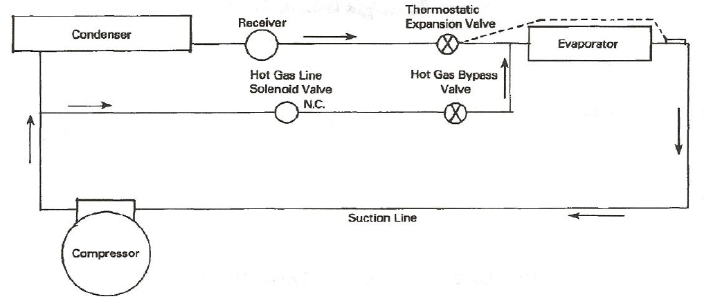
Hot gas bypass or HGBP for short, utilizes a mechanical method for capacity control that prevents the refrigeration compressor from cycling frequently. In a given 24 hour period, a compressor may cycle twenty times or even greater given the cooling demands of the refrigerated space. The cycling of the compressor leads to large differences in the temperature of the refrigerated structure which is unacceptable in some applications such as blood and plasma banks. This method essentially hinders the refrigeration system from turning off even after the cooling requirements from the refrigerated space have been satisfied. We provide the following refrigeration diagram to illustrate how a HGBP mechanism works.

The following refrigeration diagram, although simple, shows the intuition behind a HGBP method for cycle control of a refrigeration system. There are different methods to piping a hot gas bypass system however the one displayed here is most typical in the industry. Hot gas bypass begins to influence the system once the cooling demands of the refrigerated structure have been satisfied. Once the cooling load has been satisfied, a solenoid closes which restricts flow of refrigerant to the evaporator as discussed in Section 1.2.1. Instead of the compressor pumping down as in the previous refrigeration diagram, the hot gas line solenoid valve opens and feeds the evaporator with hot gas. By feeding the evaporator hot gas a “false load” is created in the room which eventually leads to the thermostat calling for cooling. Once the thermostat calls for cooling in the room the normal refrigeration cycle begins again.
Energy savings are realized here by preventing the compressor from cycling. As discussed in the introduction, energy demand is realized every time the compressor starts. Hot gas bypass prevents the compressor from turning off therefore the number of starts are greatly reduced. The HGBP method may prevent the compressor from cycling however energy is still being consumed from the compressor constantly running. May it also be noted that since the compressor is prevented from cycling by HGBP, that there is less wear and tear on that compressor. More recent electronic and mechanical methods not only prevent the compressor from cycling, but also address the issue of the compressor constantly consuming energy.
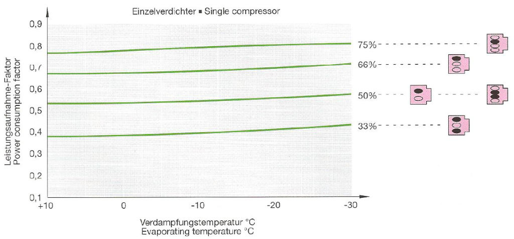
Several types of refrigeration compressors, much like an automobile, utilize pistons or cylinders to compress the refrigerant gas. In the industry today, these compressors have two, four, six, or eight pistons typically. Cylinder unloading is used for capacity control by “[interrupting] the gas flow, and the corresponding pistons operate in the ‘idle mode’ without gas pressure” (Bitzer USA pg 8). During full load operation, the compressor will operate with all cylinders. However, during part load operation a mechanical mechanism prevents the gas flow to certain cylinders putting them in an idle state. For example if we were to have a two cylinder compressor, cylinder unloading would prevent gas flow to one of the cylinders when refrigeration conditions allowed for part load operation. Cylinder unloading is a relatively simple idea which keeps the compressor running through part load operation instead of turning off. Not only does it prevent the compressor shutting off, but it also cuts down on the compressor energy consumption. A refrigeration diagram from Bitzer USA illustrates the energy savings from compressor cylinder unloading.

From the diagram above, the pink blocks on the right illustrate different compressor sizes with different amounts of pistons. The black ovals illustrate an unloaded cylinder that is idle while the pink ovals show compressor cylinders that continue to compress refrigerant gas. A single compressor has a power consumption factor of 1 during full load operation i.e. all cylinders are being utilized. From the diagram above, one can see that the power factor varies based on how many cylinders of a compressor are unloaded. For instance with the three cylinder compressor, with two cylinders unloaded, it achieves a power consumption factor of approximately 0.4 at ten degrees Celsius. May it be noted that the power consumption factor is dependent upon the evaporating temperature since the compressor requires more energy to compressor lower temperature refrigerant gas. Therefore, cylinder unloading not only cuts down the amount of cycles a compressor experiences, but also the power consumption of the compressor during part load conditions. Hence, cylinder unloading is more efficient than the hot gas bypass method. Unfortunately, cylinder unloading can only be applied to large compressors therefore it is not suitable for every application. However, it may be noted that there are other ways to “unload” compressors without cylinders using different methods that will not be discussed in this thesis. A new electronic method has been developed recently which provides a larger application range than cylinder unloading.
A compressor with a frequency inverter or a variable speed compressor utilizes an electronic control that varies the speed of the compressor based on the cooling demands of the refrigerated space. The electronic control varies the speed at which the compressor motor runs at providing stepless capacity control of the refrigeration compressor. This differs from the cylinder unloading method because the capacity reduction of the compressor is directly related to the number of cylinders the compressor has. Therefore, cylinder unloading provides stepped capacity control. Note with variable speed compressors the definitions of full load operation and part load operation vary from the definitions in section 1.2.3. Here full load operation is when the compressor is running at its maximum designed speed. Then, part load operation occurs when the compressor is running at some speed less than its maximum.
Some manufacturers incorporate a soft starter into their electronic control which prevents the compressor from drawing large amperage to start which relates to a large spike in energy demand. In addition some manufacturers claim that by utilizing a variable speed compressor, the capacity of the compressor can be reduced to ten percent of the published full load capacity. Therefore, when a normal refrigeration system would complete its cycle, a system utilizing a variable speed compressor could run at reduced load until higher cooling demands are realized. Hence, similar to the cylinder unloading method, these compressors with electronic speed control prevent the cycling of compressors as well as reduce the energy being consumed by utilizing part load operation. Unfortunately, compressors with variable speed drives or frequency inverters are expensive compared to their mechanical counterparts. Therefore there is some debate as to whether or not the costs inhibit the benefits of variable speed compressors.
Through this section we discussed several ways to promote cost savings using electronic and mechanical means to control the cycling of the compressor. HGBP utilized a mechanical method that kept the compressor from cycling which in turn causes large energy demand spikes. The two latter methods utilize mechanics and electronics to not only prevent the cycling of the compressor but reduce their energy consumption as well. All of these methods have their own limitations due to application and cost. However these methods illustrate the importance of reducing the amount of cycles of a refrigeration compressor which leads to possible cost savings which we investigate later.
- SST = Saturated Suction Temperature
- TD = Temperature Difference = Room Temperature-SST
- 7° – 9° TD ≈ 95% Relative Humidity (Flowers – high humidity, low velocity)
- 8° – 10° TD ≈ 90 – 95% Relative Humidity (For minimum amount of moisture removal. All low temperature freezers. Fresh vegetables, produce, and chill rooms.
- 10° – 12° TD ≈ 80 – 85% Relative Humidity (General Storage. Convenience store coolers. Packaged meats and vegetables.
- 12° – 16° TD ≈ 70 – 75% Beer, wine, potatoes, onions, and tough skin fruits and vegetables.
- 16° – 20° TD ≈ 60 – 65% Candy, film, cutting and preparation rooms.
- Standard selections are around a 10° TD. Any special applications should be directed to RSC such as preparation rooms and beer and wine rooms.
- City Water Cooled
- Cooling Tower Cooled
- Chiller Loop Cooled (if chiller loop need to know temperature and type of fluid and if glycol what type, temperature, and percentage)
- Depending upon conditions a larger condenser may be necessary with glycol loops
- Standard Condensing Unit Selection at 95° Ambient
- For each increase of 5° F capacity decreases by 3%
- For ambient 110° F or greater special design must be considered such as larger condensers or increasing the base size.
- Evaporator to be matched to condensing unit capacity only after condensing unit capacity has been de-rated.
- To de-rate capacity of condensing unit for 50 Hz cycle
- To de-rate capacity of evaporator for 50 Hz cycle
- Systems must be carefully selected for 50 Hz cycle in order to ensure a properly balanced system.


